Equivalent circuit models define the entire I-V curve of a cell, module, or array as a continuous function for a given set of operating conditions. One basic equivalent circuit model in common use is the single diode model, which is derived from physical principles (e.g., Gray, 2011) and represented by the following circuit for a single solar cell:
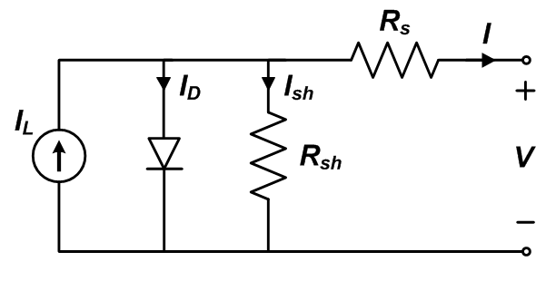
The governing equation for this equivalent circuit is formulated using Kirchoff’s current law for current $$I$$:
$$I=I_L – I_D – I_{sh}$$
Here, $$I_L$$ represents the light-generated current in the cell, $$I_D$$ represents the voltage-dependent current lost to recombination, and $$I_{sh}$$ represents the current lost due to shunt resistances. In this single diode model, $$I_D$$ is modeled using the Shockley equation for an ideal diode:
$$I_D=I_0\left [\exp \left (\frac{V+ IR_{s}}{nV_{T}} \right ) -1 \right ]$$
where $$n$$ is the diode ideality factor (unitless, usually between 1 and 2 for a single junction cell), $$I_{0}$$ is the saturation current, and $$V_{T}$$ is the thermal voltage given by:
$$V_{T}=\frac {kT_{c}}{q}$$
where $$k$$ is Boltzmann’s constant $$1.381\times 10^{-23} \; \textup{J/K})$$ and $$$$ is the elementary charge $$(1.602 \times 10^{-19} \; \textup{C})$$.
Writing the shunt current as $$I_{sh = \left(V+I R_S\right) / R_{sh}$$ and combining this and the above equations results in the complete governing equation for the single diode model:
$$I={I_L} – {I_0} \left[ \exp \left( {\frac{{V+I{R_s}}} {{n{V_T}}}} \right) -1 \right] – \frac{{V + I {R_s}}} {{{R_{sh}}}} \qquad$$
The five parameters in this equation are primary to all single diode equivalent circuit models:
- $$I_L$$ : light current (A)
- $$I-0$$ : diode reverse saturation current (A)
- $$R_s$$ : series resistance ($$\Omega$$)
- $$R_{sh}$$ : shunt resistance ($$\Omega$$)
- $$n$$ : diode ideality factor (unitless)
For a photovoltaic module or array comprising $$N_s$$ cells in series, and assuming all cells are identical and under uniform and equal irradiance and temperature (i.e., generate equal current and voltage), $$I_{module} = I_{cell}$$ and $$V_{module} = N_x \times V_{cell}$$
The single diode equation for a module or array becomes (Tian, 2012):
$$I_{M} = {I_L} – {I_0} \left[ {\exp \left( {\frac {{{V_M} + {I_M} {N_s} {R_s}}}{{n{N_s}{V_T}}}} \right) -1} \right] – \frac{{{V_M} + {I_M} {N_s}{R_s}}}{{{N_s}{R_{sh}}}} \qquad$$
where $$I_M$$ and $$V_M$$ are the current and voltage, respectively, of the module or array. Care should be taken when implementing model parameters, as they are either applicable to a cell, module, or array. Parameters for modules or arrays are strictly used with the single diode equation for $$I$$ , which is the more commonly implemented form.
In some implementations (e.g., De Soto et al., 2006) the thermal voltage $$V_T$$, diode ideality factor $$n$$, and number of cells in series $$N_s$$ are combined into a single variable $$a$$ termed the modified ideality factor:
$$a \equiv {{N_s n k T_c} \over q}\qquad$$.
Content for this page was contributed by Matthew Boyd (NIST) and Clifford Hansen (Sandia)
The following equivalent circuit module models are described. These models have been proposed with different sets of auxiliary equations that describe how the primary parameters of the single diode equation change with cell temperature and irradiance. Module models, or those with parameters applicable to a module using $$I_M$$, are examined here instead of those for cells or arrays because module models are the basic performance models used for modeling arrays in PV modeling software packages.