Ray Tracing Work at the University of Iowa
COMSOL is a finite element method (FEM) solver and the Ray Optics Module can be used to model electromagnetic wave propagation in systems in which the wavelength is much smaller than the smallest geometric detail in the model. The electromagnetic waves are treated as rays that can propagate through homogeneous or graded media. Because it is not necessary to resolve the wavelength with a finite element mesh, ray trajectories can be computed over long distances at a low computational cost. Rays can also undergo reflection and refraction at boundaries between different media.[1] COMSOL’s Ray Optics package uses a forward ray tracing model that can run on a high performance computing (HPC) platform to model large domains and many separate rays.
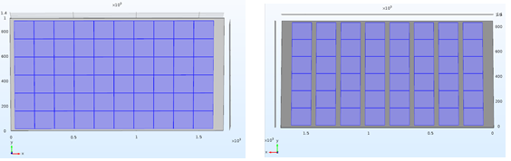
Preliminary simulations of backside irradiance have been made to explore the effect of cell spacing within a bifacial module. For example, Prism Solar offers two versions of its bifacial solar modules. One fills the module area with 60 PV cells and the other uses 48 cells in the same area but includes transparent spaces between cells to allow more light to pass through the module.
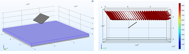
The modeling was performed assuming a single module was installed in landscape orientation at 35° tilt (Albuquerque’s latitude) angle and 1 m above the ground surface (measured from the bottom edge of the module). Three different types of roof surfaces were considered: soiled beige roof (37% albedo), clean beige roof (55% albedo) and white beige roof (83% albedo), based on measurements made by NREL.
In this preliminary example, rays are released with an incidence angle of 0° to the module surface (this represents the solar position at solar noon on the equinox). At this stage, only direct beam radiation is simulated (diffuse radiation is ignored).
Released rays get scattered at the module and ground surfaces and reach the back of the module later in time (in this case, because rays are normal to module, there is no refraction by module). Released rays find their way to ground except when they are absorbed by the cells in the module.
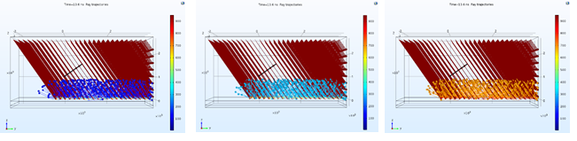
Initial simulations were run on a workstation and thus used a coarse grid and a sparse set of rays. This results in non-uniform irradiance patterns caused by the coarse grid. Future runs will use the Univ. of Iowa’s HPC, which will result in more accurate and smoother results. The initial coarse results are shown below.
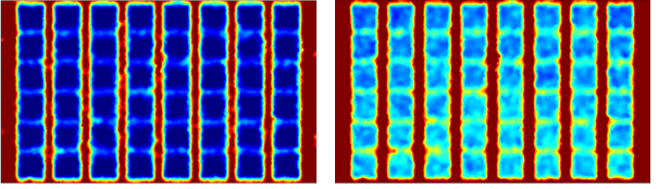
The initial results are shown as maps of cumulative light passing through an imaginary plane coplanar with the back of the bifacial module. Simulated sun rays hitting the module get scattered by the module and ground. Scattered rays from the ground reach back-side of the panel later in time and deposit additional power on cells. Therefore, we determined the power intensity on the back of the module at a time (8 ns) when the sun rays pass through the panel through the spacing between the cells (left figures at 8 ns) and after (20 ns) the rays are reflected back from the ground to the back of the panel (right figures). Due to high energy absorption of the silicon cells, rays only passes through the gap between the cells, which is filled with EVA (ethyl vinyl acetate). Difference of power intensity in the left and right figures shows how much additional power reaches the back of the cells in the case of a soiled beige roof, clean beige roof and white roof.

48 cell module: Deposited ray power intensity (/2) after front-side irradiance and before backside irradiance (left) and after backside irradiance (right) for soiled beige roof (reflectivity of ~37%)
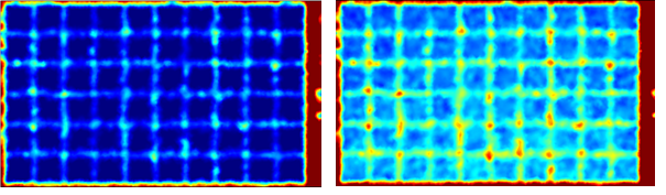
60 cell module: Deposited ray power intensity (/2) after front-side irradiance and before backside irradiance (left) and after backside irradiance (right) for soiled beige roof (reflectivity of ~37%)
48 cell module: Deposited ray power intensity (W/) after front-side irradiance and before backside irradiance (left) and after backside irradiance (right) for white roof (reflectivity of ~83%)
60 cell module: Deposited ray power intensity (W/) after front-side irradiance and before backside irradiance (left) and after backside irradiance (right) for white roof (reflectivity of ~83%)
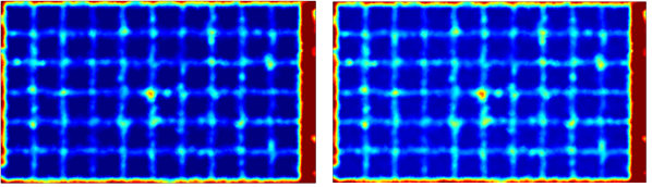
Below are backside irradiance maps (difference of top figures) for two types of roofs.
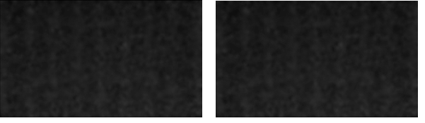
Backside irradiance maps for the souled beige roof (37% albedo). Left is for the 48 cell module with average intensity of 57.11 W/m^2 and right is for 60 cell with average intensity of 52.49 W/m^2.

Backside irradiance maps for the white roof (83% albedo). Left is for the 48 cell module with average intensity of 289.70 W/ m^2 and right is for 60 cell module with average intensity of 257.66 W/m^2
Including gaps between cells in bifacial modules increases the bifacial efficiency but is unlikely to offer significant economic advantages in energy costs over tightly spaced cell versions. However, in certain applications, such as carports, patio covers and skylights, the added light transparency may offer benefits beyond the pure cost of energy.
Ray tracing methods, such as COMSOL’s Ray Optics Module are a promising method for evaluating back side irradiance and thus bifacial PV performance. The University of Iowa will continue to develop more complex and sophisticated models of back side irradiance. Stay tuned for updates on results.
[1] https://www.comsol.com/ray-optics-module
This modeling work was performed by Amir Asgharzadeh Shishavan, a PhD. graduate student at the University of Iowa under the supervision of Dr. Fatima Toor.